3dprinting in Kigali (Rwanda)

After days of calibration finally our printer is up. With it’s 230X300X300 print bed it’s a beast.

If you have a project drop me a line on twitter @atilev and I’ll be happy to help with your project. As far as I know this is the only functioning printer in the country.
What can we do but not share it!

Alp

3Dprinting on mendelmax3 (what a pain)

4 months in after my move to Kigali, I heard rumors of a 3d printer roaming around. After leaving my Afinia in NYC I was desperate to get my hands on my favorite tool again. Especially in a geography where tools are scarce and supremely expensive. Later I got word of a abandoned, dis-functional 3d printer gathering dust in someone’s basement. Through some quick research, It turns out that actually a colleague of mine had acquired it and was waiting to fix it. After a few days of nagging the beast appeared in our office. A “Mendel Max 3” a complete DIY system based on the RepRap rambo board. With a massive heated print bed it was everything a maker could want. Upon quickly starting to tinker I found out the X-axis end stop was broken. Fixing this was quite easy. You simple disable end stop homing for X-Axis in the Slicer. Was I was using CURA with RepieterHost so getting to the bottom of this one was simple and sweet.

After a few initial prints with PLA I quickly found out that the feeder stepper motor on the mendel max is prone to start skipping on the 1.75mm PLA filament. Specifically with softer filaments like PLA that’s been gathering dust for some time. Initial inspection found that the filament runs through a heatsink pipe section which sits between the stepper motor and the extruder heating element. (picture)

The 30mm fan located here was actually pulling rather than pushing air around the heatsink. In the process of removing this fan I unfortunatly shorted the connection leads and blew the 15A tiny fuse. These are impossible to find in rwanda. I was able to put in a quick acting car fuse to circumvent this problem.

Keep in mind that the documentation for the mendel max is decent but there doesn’t seem to be a whole lot of them out there so you’re generally relying more so on the RepRap ultimaker documentation.

While fixing the fuses, I’m unsure what happened but the firmware got corrupted so I had to reflash the EEPROM. The problem here is that I lost all my settings for my actuator steps and acceleration values. I quickly found that prints were coming out larger on the X Y axis and Shorter on the Z axis.

After fiddling around with the parameters I found that these values work the best. One thing to note here is that repieter host will allow you to change the EEPROM parameters through it’s own UI. However I found that modifying the values through repieter host didn’t persist. This might and will drive you crazy if you don’t know that it’s going on.

Download the latest image for your reprap rambo board and open “configuration.h” in your arduino IDE.

Scroll down and you should see a section like this. Below are my parameters.

// default settings

#define DEFAULT_AXIS_STEPS_PER_UNIT {80,80,1600,99} // default steps per unit for Ultimaker/ 80 80 xy for mendelmax z 1600
#define DEFAULT_MAX_FEEDRATE {500, 500, 5, 30} // (mm/sec) // mendelxmax z-10.5
#define DEFAULT_MAX_ACCELERATION {1100,1100,10,10000} // X, Y, Z - 50 to 10 , E maximum start speed for accelerated moves. E default values are good for skeinforge 40+, for older versions raise them a lot.

#define DEFAULT_ACCELERATION 400 // X, Y, Z and E max acceleration in mm/s^2 for printing moves # changing from 1100 to 400
#define DEFAULT_RETRACT_ACCELERATION 1500 // X, Y, Z and E max acceleration in mm/s^2 for retracts

// Offset of the extruders (uncomment if using more than one and relying on firmware to position when changing).
// The offset has to be X=0, Y=0 for the extruder 0 hotend (default extruder).
// For the other hotends it is their distance from the extruder 0 hotend.
// #define EXTRUDER_OFFSET_X {0.0, 20.00} // (in mm) for each extruder, offset of the hotend on the X axis
// #define EXTRUDER_OFFSET_Y {0.0, 5.00} // (in mm) for each extruder, offset of the hotend on the Y axis

// The speed change that does not require acceleration (i.e. the software might assume it can be done instantaneously)
#define DEFAULT_XYJERK 15.0 // (mm/sec)
#define DEFAULT_ZJERK 0.2 // (mm/sec)
#define DEFAULT_EJERK 5.0 // (mm/sec)

One other thing to keep in mind with the mendel max 3 is that starting to heat the bed and the extruder simultaneously led to overheating in the 2 pin connection on the rambo board. This resulted in a small melt down and could have led to much worse things.

Happy printing and drop my a line if you need anything printed in Kigali!

Poor mans DIY Laptop Stand

Continuing on my “Poor Mans” series I found that making things with what you have at hand can be both fun and resourceful. To set the stage it might help to give some background first. Around a month ago, I left my position at Microsoft and have relocated to Kigali, Rwanda. I joined a team of inspiring people looking to reshape energy and in healthcare in Africa. They are called Great Lakes EnergyYou can check out their new website which we just launched.

Being in Rwanda you need it’s a bit harder to get some o the fancy things we might get used to at home. Amazon one click simply isn’t one click away. So sometimes you need to improvise. Since I would be working of my Acer S7 now, one of these things that I quickly found I needed was a laptop stand. I was looking for the classic macbook tilted stand that we’ve come to see as the staple of every startup office around the US.

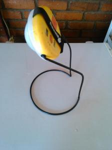
So in the spirit of DIY, I put on together with some parts I found around the office. First and foremost was using the stand of a Sunking lamp as the base. (Sidenote: the sunking lamp is an awesome 20$ solar lamp that’s incredibly durable, Something I wish we had in the states! )

sun king solar power lamp

sun king solar power lamp

Great Lakes is also a distributor of sunking lamps so we simply happened to have a lot of them lying around. I quickly realized that the bent wire stand could be perfect for this job.

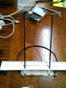
I simply needed a piece of PVC covering to act as a flange to hold the laptop on the stand. After drilling to holes in the PVC panel, I made to stoppers using masking tape.

Stand with PVC cover

Stand with PVC cover

Lastly, I needed some added weight on the bottom in order to keep the stand well balanced. I found some large steal bolts hanging around in the storage room. Strapping these to the bottom of the stand worked well.

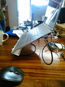
Finally it was ready for testing.

it works

it works

Looks like we have a winner.

Printing on Borosilicate Glass

Recently I decided to up my game a bit and start printing on borosilicate glass. You probably know this material from your mom’s pyrex cake pans. Due to its extremely low thermal expansion it has been a favorite for applications requiring smooth surfaces and lots of heat.

Prior to using borosilicate, I was contently using the TAK surface print surface provided by Afinia. Though, the TAK surface has incredible adherence properties. These properties were a bit too good at times. It was common that I would find the adherence so strong that the printed models would get damaged while trying to remove them from the print bed. An extremely annoying problem to have. Even though the pad lost its adherence property as I did more prints, it was still producing an uneven looking on the print bed facing side of the model.

http://store.afinia.com/BuildTak-Platform-Surface–3-Pack_p_45.html

Prior to switching my print bed I did a quick survey of my other options out there.

Some of the options are

I decided to try borosilicate after years of using masking tape and builtak. Though I was pretty proficient at using both surfaces I didn’t like the final finish I got on the builds. It was common I would get bumps on the bottom surface as well as simply adherence problems and failed builds.

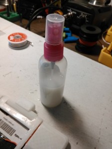
I went with borosilicate because of the price and the amount of knowledge online. I also like the idea of printing on a completely flat and smooth surface. The major caveat with using a glass composite is the need for a surface coating. This is something you’ll find most people refer to as coating the surface with an ABS Slurry. This is simply a fancy word for some left over ABS dissolved in Acetone solution. This is a solution which you need to apply on the glass prior to printing else you’ll quickly find that your print is not sticking to the surface. I found a very nice way to apply the slurry is with a spray bottle.

I found this guy at my local pharmacy where they sell travel bottles.ABS Slurry in spray bottle

Acetone is simply nail polish but don’t do what I did and simply go but some nail polish at your drug store. Nail polish actually has a very low amount of acetone and will not do the job. Simply stop by home depot and check your solvent aisle.

To get started all you need to do is apply a very thin coat of the slurry on the borosilicate glass. Simply spray a few times creating a super thin coat on the surface. Be careful not to inhale the slurry vapors. Though Acetone is note very toxic keep in mind that this slurry contains dissolved ABS which you might inhale. I use a full face mask when I’m using the sprayer. The sprayer will simply apply a super thing coat of abs on the print bed. Let it dry and start heating the bed.

Using any surface will not compensate for having a uneven surface so make sure that your print bed is completely level prior to printing.

Now my prints come out with a super shiny finish on the bottom. Now I simply ask myself why didn’t I do this before?

Nice and shiney

Look at that. Smooth and shiney : )

Alp

Hololens and Microsoft

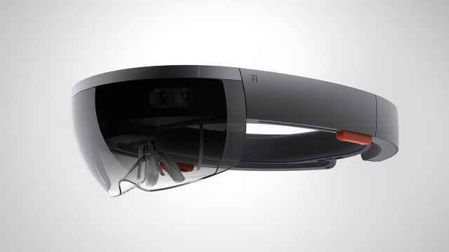
A very odd thing happened yesterday. I met a few of my friends after work where I casually walked in a brief moment after small talk I started to get bombarded with questions. Suddenly all of them started  asking me in disbelief and excitedly  “Is HoloLens a real thing” . Expressions like “if it does 1% of what they claim its amazing”  showed the excitement this was stirring. Having worked at Microsoft 7 years at Microsoft these were questions that the seasone microsoftie will agree, are quite foreign in nature..

Microsoft-HoloLens-RGB-640x360

I’ve seen an era in the past where Microsoft had put out incremental products year over year. Simply improving them slightly and trying to fill in the feature gaps between its competitors. The question of “why Microsoft” became increasingly difficult to answer. I could say “because it’s more beautiful” or “because you’ll have better market share”. These were responses that never made me content.


Now, I see in front of me a Microsoft that’s not tied to the grips of a keyboard and mouse. A Microsoft that no longer wishes it were the 90’s. Today is a day were Microsoft has broken past is legacy idea’s and has decided to move in a direction where it is bold enough to take part in the shaping of our future.


Imagine, rearranging your apartments furniture simply by moving your holographic furniture pieces around. Imagine, Taking apart or collaborating with friends in new projects that in the past you possibly couldn’t do. All this, coming at a moment when google glass was put to sleep is critical. The fact is , I really didn’t enjoy glass as a mainstream product however I still loved the utilitarian potential of glass.


As a paraglider pilot the first thing I wanted to see was someone building a vario application with glass. I imagined, I could find the best thermals without ever looking down this ways. However, Google chose to make it a mainstream product which in my opinion was the biggest mistake. People aren’t accustomed to inherent drastic changes like these and the difficulties to making paradigm shifts in what’s accepted technology.


The possibilities with Holo seem vast even with 10% of the promised final product becoming a reality. We really need an open API and an intuitive SDK that will make this as far reaching as it should . I’m confident that Microsoft has realized the importance of this and that’s why it’s coupling the API’s to windows 10.


It’s flattering to see the craziness in the labs of MSR finally getting to hit the street. I’m humbled by the progress and the vision this company has.


Alp

ABS Welding for 3dprinted objects

Recently, a close friend of mine sent me a video showing a method to fuse ABS printed parts together. Generally, with 3d printing, as the objects being created get further complicated , it’s a common requirement to print them as multiple part and  use some sort of adhesive to bring them together.

ABS Filament fusing is just like welding. Though, instead of using electricity to arch and thus cause heat, we are looking at using a dermal to cause heat through friction.

It’s a very straight forward process and works very well! I’ve included a video of me demonstrating after a recent test. The results are far better than using a hot glue gone or simply super glue.

A quick final  note: I’m using ABS filament for this. In principle I don’t see why PLA shouldn’t work though I haven’t tried it. If someone does I would love to hear their experience.

Building an FPV racing drone Part 3

If you’ve come this far, this means you’re almost done with building your FPV drone.

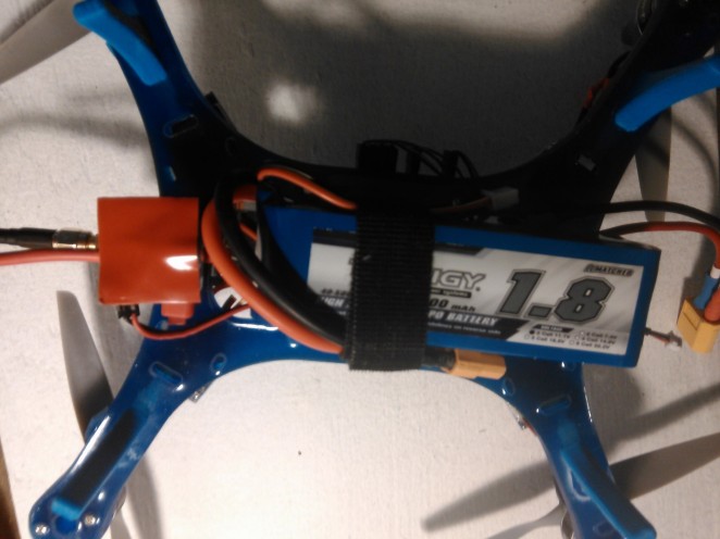
A quick anecdote before we get started. While doing my initial flight test I burned an ESC. I’ve also decided to pull the power for the FPV transmitter straight from the battery rather than the ESC as I feel this might be the culprit for my ESC burning.

O simply go back to your wiring and create another splice to pull power for the transmitter.

WP_20150104_007 WP_20150104_005

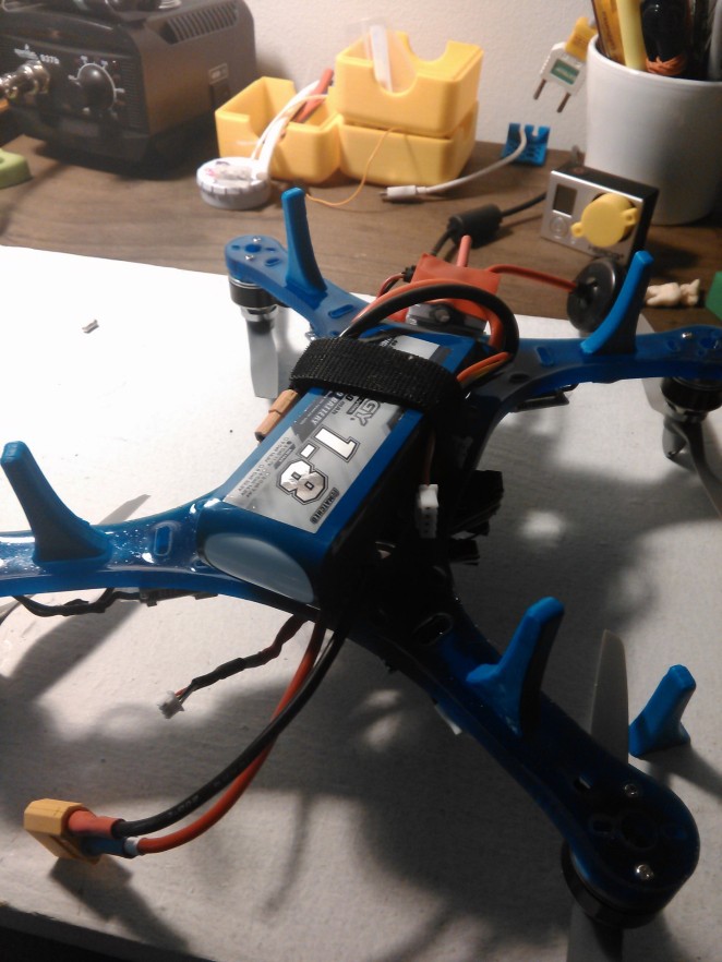
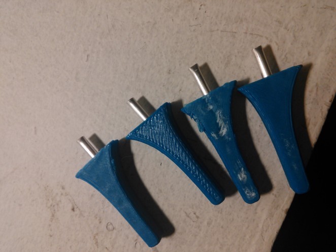
You might have notice that I’ve added some gears. This is optional. However, it makes take offs and landings a bit more stable.

I’ve uploaded the landing gear assembly to Thingiverse here: http://www.thingiverse.com/thing:621393

You can print your own. It uses a 3mm aluminum pipe and 2mm screws to hold it in place (M2x12mm Bolt) use a bit of Loctite to prevent wiggling.


These are the same screws that are used to hold your motors in place.

WP_20150104_004


Looks like you’re ready to almost fly now. We’ll have to verify a few things prior to flying.


1-Calibrating ESC

2-Calibrating flight controller

3-Calibrating Receiver controls


You can start by downloading OpenPilot GCS here: http://wiki.openpilot.org/display/BUILDS/OpenPilot+Software+Downloads

Once you get this installed you’ll notice a usb port on your flight controller time to plug this guy in. At this point make sure you have your props off the quad as this can cause major problems.

You’ll soon be needing the battery to power the ESC’s so make sure you have it charged and ready to go nearby.

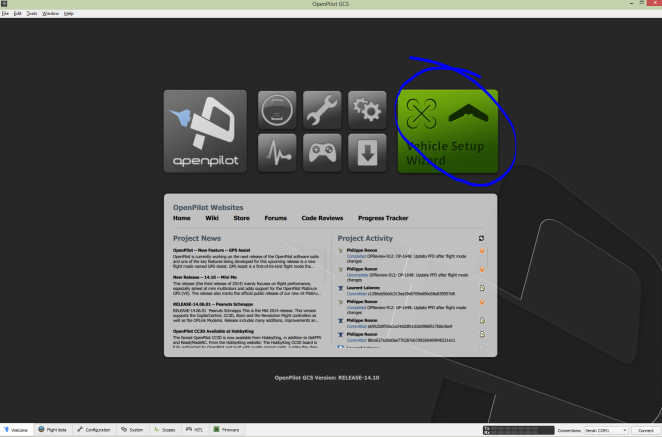
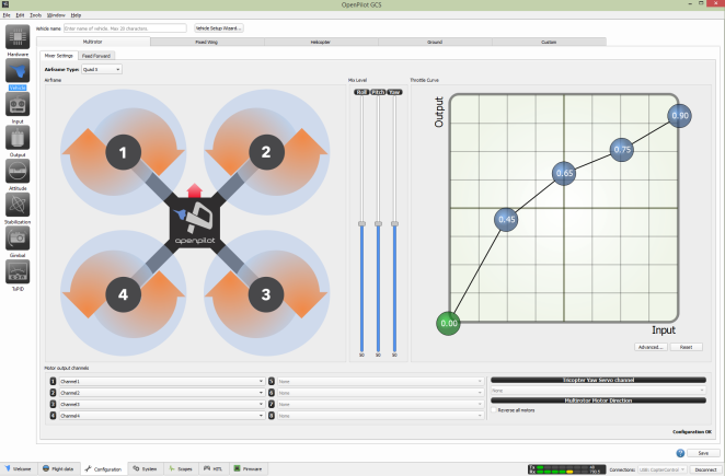
Once you launch Openpilot GCS connect your usb and start the “Vehicle Setup Wizard”

step1

Here you’ll first be updating the firmware on your cc3d board so simply go through that process.

-Next, you’ll be talking about choosing and calibrating your ESC’s. Here make sure you choose PWM as the input signal configuration

-Quadcopter as vehicle type.

-Quadcopter X has the quad type

-and 490MHZ for the type of ESC. (rapid ESC)

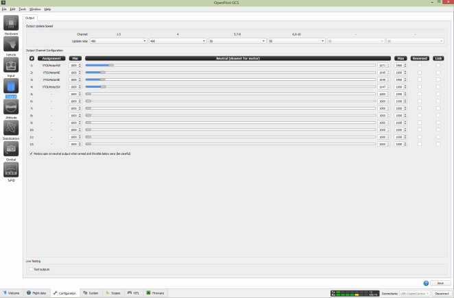
Next get your battery ready you’ll be calibrating the ESC’ simply follow the steps on screen and go through all the steps.


Last you’ll move on to the Receiver configuration. This is important. Make sure you have the battery plugged in while doing this.


One interesting thing is to make sure you have your controller in Acro mode NOT helicopter mode. Simply follow the prompts on screen to calibrate.


One thing to take not of is my Flight mode switch didn’t register during calibration so I simply used another switch on the controller for this purpose. I went with a 2-state switch but since I plan on using a single flight mode for now it should be fine.


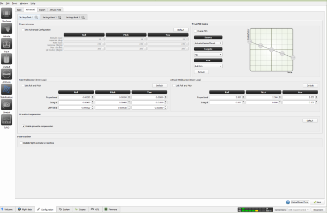
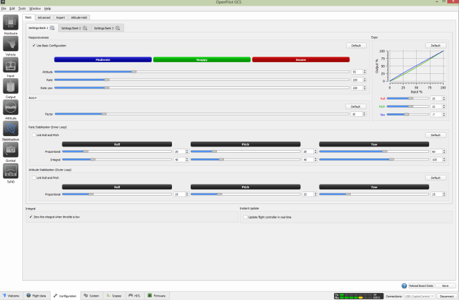
After this It make sense to reduce the aggressiveness of some of the stability parameters.

Here are a few screenshots from how my settings look. I suggest starting with the less aggressive and going up from there.

gcs_stabilzation gcs_stabilzation_basic gcs_throttle gcs_idle_throttle


Pre – flight check:

  • Make sure all your props are turning the proper way. So you need to have the proper prop on the proper engine. This is a bit confusing but once I had the proper configuration I simply wrote with a sharpie on my ESC and props in case I need to remove them. (which I actually did)
  • Make sure you got your arm setting correct on your transmitter.
  • Make sure all cables and ESC’s are mounted properly and nothing is going to get in the way of the turning props.


And here is a video of the maiden flight. Be sure to time this flight to understand the endurance of your quad.

Trouble shooting?

Drop your question in the comments area.

Happy Flying!


Alp

Setting up your self hosted WordPress site

Azure dashboard url settings

Azure dashboard url settings

Happy New year! With a new year I decided to move my blog to my own hosting instead of using the wordpress.com. I figured that since I have a nice domain and some hosting on azure, why not take advantage of it?  In doing so, I figured this could be a great piece of knowledge, for those people who are also hosting on wordpress.com and would like to self host.


Now Let’s get to the beef.


I’ll go over how to setup a wordpress site on azure and forward a custom domain to it in this tutorial. The reason I’m using azure as

  1. It’s super simple to do a self-host
  2. You can use many other features in azure if you’d like to
  3. I work for Microsoft : ) and azure is quite a cheep option.


I’ll be using azure websites for this as it provides the easiest maintenance and setup option. Setting up the server literally will take me a few clicks, it will also be very cheap (free if you have some bizspark credits hanging around)

  1. First step is to head over to the azure portal login with your existing account or create a new one.
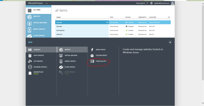
  2. Once you’ve done that you can hit the plus sign on the bottom and create a new website. Azure is kind enough to offer a template for wordpress sites so this will be quick.

    start by creating a new website service from gallery

    start by creating a new website service from gallery

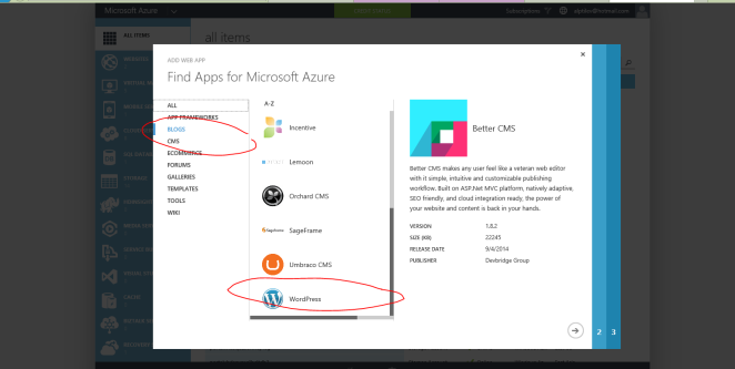
  3. In the next menu that pops up you’ll choose blogs and scroll down on the list to WordPress. wp2
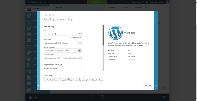
  4. I’m now naming by demo site atilev which would put it at http://atilev.azurewebsites.net.wp3
  5. You will be prompted to create a database. Since WordPress uses MySQL you’ll have to use clear dB. This will happen automatically for you. You all you need is to choose the name from the dropdown.
  6. Go ahead and hit create, check the box on the bottom of the last page saying you agree to ClearDB’s terms and you’re good to go. Once the website should be up shortly and you can go to http://<youwodrpesssitename>.azurewebsites.net and start the setup. You should be seeing a screen like this that will be asking you to create a username and password for your worddpress site.
  7. If you’re not you’ve done something wrong. Go back.
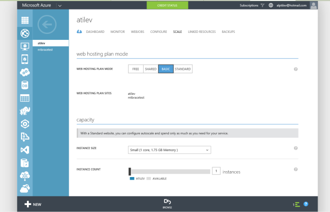
  8. To setup a custom domain for you wordpress site you’re going to need a few things. First you can’t use the FREE tier of azure websites so you’ll have to upgrade to the standard or basic tier. You can do this by going to your deployment and going to the Scale page. The small instance works fine for me as it keeps my costs down. If you have a lot of traffic you might want to increase this.wp4
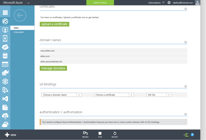
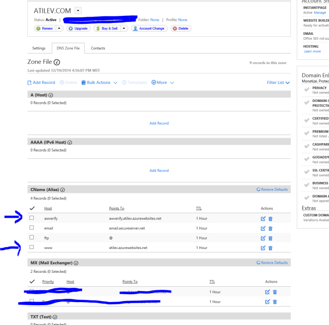
  9. After this you can navigate to the configuration tab and scroll down until you find the domain names section When you click on “manage domains” you’ll be provided instructions on a few ways you can verify that you own the domain. At this point you’ll need to log into your domain provide like godaddy.com or namecheap and add a CNAME record that points your domain to the azure website. Keep in mind this took around an hour for me so take a coffee break after you put in the CNAME record. You can only enter in your domain name on the azure portal once azure is able to verify it.
    Azure dashboard custom URL settings

    Azure dashboard custom URL settings

    Godaddy CNAME record settings

    Godaddy CNAME record settings

  10. Once you’ve verified that your domain is now resolving azure service you can go ahead and add it.
  11. One last thing now you can log in to the admin portal of your WordPress site by going to http://www.yourdomain.com/wp-admin
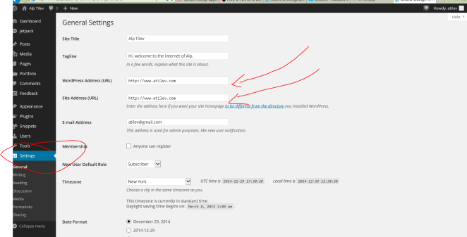
  12. Simply login the credentials you setup in step 6. Once you’re in you should be seeing your admin panel Here you’ll need to set things up but first go to the settings page and click on general settings. You’ll need to put in the address for your website so that WordPress can display the proper urls when navigation occurs. Here how my setup looks:

    WordPress settings

    WordPress settings


With this final step, you should be done! Blog and post the night away. If you have any questions feel free to post the in the comments. You’ll see that my posts are a bit stale currently on atilev.com but that should change soon.


Alp


Building a FPV racing drone Part 2

Once you have all your parts in order you can start your assembly

Start you assembly by putting together the ESC’s I noticed that the 12A hobbyking BEC I’m using are not Simon K flashed so I’ll go into the details of that further but not letting it stop my right now.  I later witched these out with Afro 12A ESC’s that can be found.

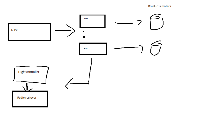
First we need to create the power distribution circuit.

power_diagram

If you’re not using a power board get your soldering iron ready as were going to be using it a lot.
Simply put the power flows through the ESC’s to the Flight controller to the receiver

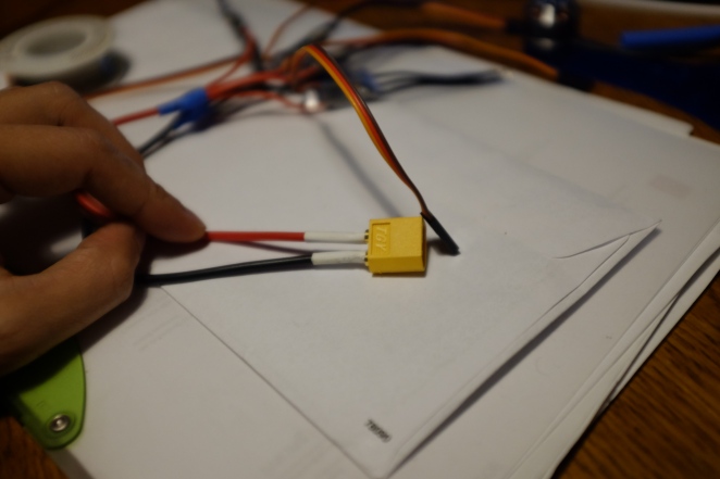
Start by Soldering some 16AWG wire to your Xt60 battery connector. I had a bit of trouble finding good sized heat shrink wrap to put around  the  connection points.

power_connector

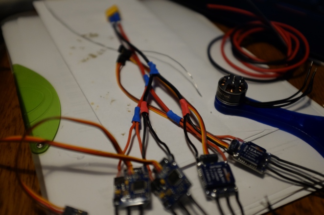
Second you need to cut the 16AWG   wire to form 2 different branches so you can distribute the power to each ESC.

esc_power

I did this by branching out the positive side and the negative side to two smaller branches.
Once the ESC’s are sorted out we can move across to connecting them to the motors.
This is a bit of a tedious process as you want to cut the lengths of the motor control wires and the motor wires such that there is minimal slack between the esc and the motor.

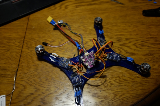
Below you can see this after the soldering. Take note to remove the power cables from all but one ESC going to the flight controller. The cable color coding is as below. So cut the Brown and red from all esc signal cables but one prior to plugging in. This is explained in the cc3d wiki http://wiki.openpilot.org/display/Doc/CopterControl+Hardware+Manual
ESC signal wires:
Brown – Red – Orange
Neg – POS – Signal

fully_connected

Before we zip tie everything down I’ll make sure to check that everything is working. Remember to cross the wires of 2 opposing ESC to give counter rotation to the props on opposing ends. This will save you some time future debugging hours.

Also ideally you would like the arrow on your CC3D board facing the front of the quad but again this is not necessary as you can tune this later in through the openpilot software. JUST REMEMBER THIS BEFORE YOU FLY. (more details on CC3D board here http://wiki.openpilot.org/display/Doc/OpenPilot+Quick+Start+Guide)

At this point you can go ahead and download GCS here : http://www.mavlink.org/downloads

Simply step through the Aircraft setupwizard. This will make you update your CC3D firmware , calibrate your ESC’s and make sure all you motors are oriented correctly and spinning the right way.

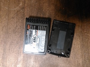
You can now go ahead and plug in your receiver. I removed the casing from mine to make it smaller and easier to mount. I chose to mount it on top of my CC3D board with the dual sided foam tape.

WP_20141219_007
As a transmitter I got the  Turnigy 9x reciever priced at 50$ at hobby king this is a steal. This also comes with a 9 channel receiver.
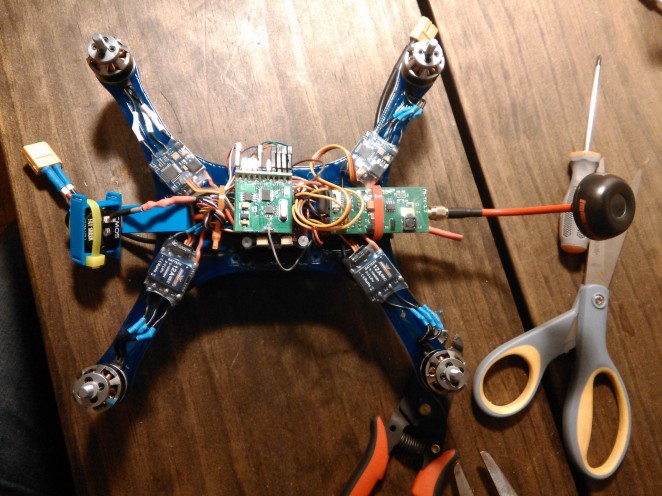
Here are a few pictures of the setup. I have the FPV transmitter mounted in the back along with the receiver antenna.  I’m thinking this might cause some interference but we’ll see.

WP_20141217_001

At this point we’re almost ready to fly. You’re probably thinking “well , were is my camera?”
This is one step before that. We’ll be needing to calibrate the transmitter and the quad before we’ll be mounting our camera.

I’ll be going over pre flight and final FPV pre checks in the Final and calibration and 3rd post : )


Alp